Magic Leap has not been forthcoming with details about how their technology works. From what little we know, it is a truly novel system with capabilities far beyond the off the shelf components consumers are accustomed to. You can’t blame Magic Leap for wanting to keep it a secret. There are many companies sniffing at their heels trying to emulate what has got people so excited. It sounds like the exact technology that Apple wishes it had. A potentially revolutionary new thing that shows signs of true innovation. It feels like it is what Microsoft was striving for with HoloLens but haven’t quite got there yet. It takes inspiration from Google Glass but is clearly gone generations beyond it.
So what is it and how does it work? I have gone through talks, patents, job applications, and the background of people working at the company to try to find out.
The Broad Strokes
Before we dive into too much detail, let’s get an overview of what this will be. Simply put, Magic Leap is building a device capable of manifesting objects into a person’s field of view with a level of realism beyond what we have seen so far from other similar devices. Magic Leap will come in two parts: a pair of glasses and small pocket projector/compute unit, think phone-sized rectangle without a screen. The pocket unit will be connected via cable to the glasses.
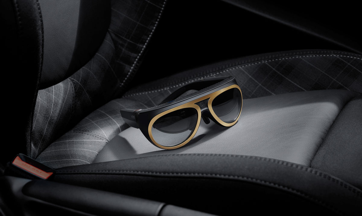
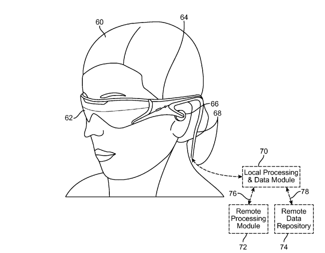
The glasses will be similar in size and design to glasses worn by people today, though they may be a bit chunkier than we are used to. The small size of the headset is the most fundamental piece of this product. It means it will be socially acceptable to wear in public and gives it the potential to have the utility and accessibility of a smartphone.
The Pocket Projector and Compute Unit
The major trick Magic Leap has been able to pull off is to remove most of the required hardware from the glasses and put it in a separate unit. HoloLens, as a counter example, does an impressive job of keeping the size down but they can only do so much as all the components are placed in the headgear. So what will the pocket unit contain? Likely the following:
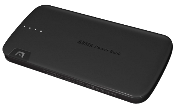
Battery
This will take a similar amount of power as a modern smartphone and potentially more depending on use. If this is to replace the smartphone it will need a seriously beefy battery. My guess would be at least 5000mAh.
CPU/GPU
These will likely be the latest generation mobile CPUs. I am guessing they will source them from Qualcomm. Luckily, they will save on the need to have high end graphics processing as MR only requires the rendering of some components and not the entire scene. This eliminates the issue VR has with intense graphic processing.
RAM
Similar requirements to a smartphone. I imagine we get 3 – 4 GB,
Custom Chips
These will be needed for SLAM processing. Definitely required for placing virtual objects in the real world. They might be building this chip in house or perhaps Movidius chips or some equivalent.
4G, WiFi, Bluetooth Connection, SIM Card, GPS Chip
Camera
There needs to be a number of cameras on the glasses but this doesn’t mean that the pocket device won’t have a camera. The requirements of the cameras on the headset to do SLAM are very different than the requirements for a good consumer camera. Given size restrictions on the glasses they may forgo a high powered camera on the headset and put it on the pocket device. This would have the added benefit of alleviating privacy concerns as you won’t be able to take photographs with the glasses alone.
Laser Projector
This is the meat of their innovation. Moving the projection system off of the glasses and on to the pocket unit affords a significant size saving for the final product. The projected light is produced on the pocket device and then sent up to the headset via a fiberoptic cable. Later in the article we will go into more detail on how this works.
The Glasses
After stuffing as much as we can in the pocket component of the product, what is left for the glasses? It will need to fit the following:
This will be a traditional accelerometer, gyroscope and compass.
Headphones
Perhaps they will use bone conducting headphones as seen with google glass. This goes with their philosophy of working with your body instead of against it. Bone conducting has the advantage that you can hear the outside world as well as the played audio.
Microphone, Optics, and Cameras
The optics and the cameras are the most interesting components so let’s look at those more closely.
Optics
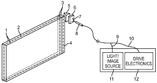
As we can see from patent applications, the optics used by Magic Leap afford considerable size advantages when compared to more traditional projection systems such as that found in HoloLens or Google Glass. The image above shows that the light source is separated from the main headset and it is how we can surmise that the pocket device will drive the light.
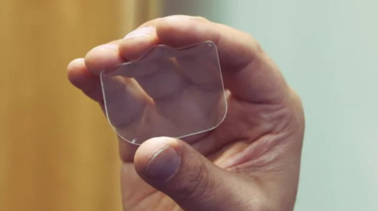
Secondly, it shows a lens system that is very small. The image is clearly not meant to be to scale but must represent the approximate sizes of the components involved. The only component we have actually seen is the photonic chip. Comparing components 5, 6, 7 and 8 (above) to the width of the chip and we start to see the sizes involved.
So what is going on here? How have they shrunk the optics so much while also claiming to achieve a light field display, high resolution and impressive field of view? The answer is two fold: The fiber scanning display and the photonic lightfield chip.
Fiber Scanning Display
 The fiber scanning display is a completely novel display system that has not been used in a consumer product before. Much of what we know of this invention comes from a patent application dating back to 2013.
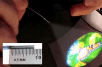
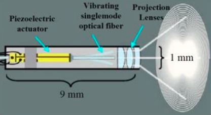
The application is from some time ago so we can expect some of the details related to the performance of the system to have changed but the broad idea likely still holds true. The system uses an actuating fiber optic cable to scan out images much larger than the aperture of the fiber itself. It works in a similar way to old style tube TV. Instead of scanning electrons, this is scanning the light itself.
By using a piezoelectric actuator to achieve this scanning, one can maintain scan rates on the order of 24 kHz. We don’t get a framerate that high though because it takes multiple passes (the patent has an example of 250 cycles) to produce a full frame. This changes how we think about resolution. With this technology, resolution is dependant on fiber scan rate, the minimum spot size the fiber can focus to (this will define pixel pitch), the number of scans to generate a full frame and the desired frame rate. Depending on how well they have optimized since this patent was filed we can expect resolution much higher than any consumer system seen today.
While resolution and framerate are crucial to creating realistic holograms, field of view is equally important. Related to this, check out this interesting paragraph in the background information section of the patent.
“The Field of view (FOV) of the head mounted display (HMD) may be determined by the microdisplay image size together with the viewing optics. The human visual system has a total FOV of about 200° horizontal by 130° horizontal (sic), but most HMDs provide on the order of 40° FOV. …. An angular resolution of about 50-60 arc-seconds is a threshold for 20/20 visual acuity performance, and it is determined by the pixel density of the microdisplay. To best match the capabilities of the average human visual system, an HMD should provide 20/20 visual acuity over a 40° by 40° FOV, so at an angular resolution of 50 arc-seconds this equates to about 8 megapixels (Mpx) . To increase this to a desired 120° by 80° FOV would require nearly 50 Mpx.”
 This puts two things into place. The first is that consumer displays are almost an order of magnitude behind what they need to be to increase FOV. This makes it clear why HoloLens is struggling so much to produce a large FOV. Second, it shows Magic Leap’s aspirations. They want to produce a field of view of 120° by 80°. This would be a larger field of view than the Oculus Rift and at far greater resolution. So have they achieved this? It is hard to say but the patent does give us some numbers to work with bearing in mind these are over 3 years old and they have likely improved the technology even more in the meantime.
Pixel pitch is the distance from the center of one pixel to the center of the next and is a limiting factor in resolution. Traditional microdisplays, like those used by HoloLens, have a pixel pitch of about 4-5 microns. This limits the resolution of these displays and thereby also limits the field of view that can be produced. The patent indicates that a scanning fiber display can produces a pixel pitch of 0.6 microns which is an order of magnitude improvement.
So what resolution does that produce? They quote a resolution of 4375 x 2300 in one section of the patent but I don’t think that tells the whole story. This is the example given for a naive approach before they start discussing multi-core fibers improving this further. I believe the resolution is much higher than that. This is crucial if we want a large field of view.
Finally given the stated aspiration of a 120° field of view this line is of particular note:
“The above described technologies facilitate an ultra-high resolution display that supports a large FOV in a head-mounted or other near-to-eye display configuration.”
I think this all but confirms we will have a FOV that is, at minimum, far greater than 40° and I don’t think it is crazy to think it is approaching the stated goal of 120°. If I was a gambling man, I’d put my money on 90°.
Photonic Lightfield Chip
When I first heard Rony Abovitz call his lens a “photonic lightfield chip”, I groaned. Not another crazy name for something that already exists. It is called a lens Rony! But the more I researched it the more it became apparent that it is in fact much more than a simple lens. So, how does it work and why is it far more interesting than a simple lens? Let’s talk about diffractive optical elements.
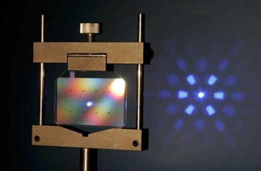
Diffractive Optical Elements (DOEs) can be thought of as very thin “lenses” that provide beam shaping, beam splitting and diffusing or homogenizing. Magic leap utilized linear diffractive grating with circular lens to split the beam wave front and produce beams with desired focus. That is to say it directs the light to your eyes and makes it look like it is in the correct focal plane. But this is far easier said than done and it is by no means easy to say. The patent document that I am pulling all of my information from is verbose to say the least.
To build a light field, Magic Leap has set up a photonic chip with two separate components. One element (6 in the diagram) which takes the projected light and inserts it into the second element (1) which redirects the light into your eyes.
Both components make use of DOEs to do their job. The main drawback of DOEs is that they are highly tuned to do one specific job. They cannot operate on different wavelengths and they cannot change properties to allow for different focal points in real time.
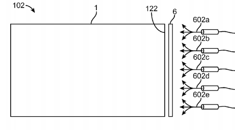
To solve this, Magic Leap has layered a number of DOEs together into the larger lens-like component that are tuned to different wavelengths and focal planes. These DOEs are extremely thin, they are on the same scales as the wavelength of the light they are manipulating so this doesn’t add much bulk to the apparatus. Here is where the chip nature of this optical system comes in. Magic Leap is able to turn on or off the different layers of DOEs. By doing this they can change the path in which the light reaches your eyes. This is how they change the focal point of the image and achieve a true light field. As the patent says:
“For example, a first DOE in the set, when switched ON, may produce an image at an optical viewing distance of 1 meter for a viewer looking into the primary or emission face of the planar waveguide. A second DOE in the set, when switched ON, may produce an image at an optical viewing distance of 1.25 meters.”
It might seem that this is highly limiting as you would need a large number of layers to produce the full range of focal points but this isn’t the case. Different combinations of DOEs in conjunction also produce different output states. So it isn’t one focal plane per DOE, it is one per combination of DOEs.
[gfycat data_id=”TerrificBountifulIndochinahogdeer”]
Changing the set of DOEs that are currently active changes the path in which the light exits the Photonic Lightfield Chip, as shown in the GIF above. They will likely have more layers than the number depicted here but how many is anyone’s guess.
Finally, we see how Magic Leap manages to create black with light as they have claimed to be able to do in the past. If we take a DOE on the outer edge of the lens and one on the inner edge we can use them to cancel out light similar to noise cancelling headphones. From the patent:
“Such may be used to cancel light from the planar waveguides with respect to light from the background or real world, in some respects similar to noise canceling headphones.”
So, why is this a chip? Well, a typical electron chip changes the flow of electrons based on certain conditions. The Magic Leap photonic lightfield chip changes the pathways of photons based on certain parameters. Sounds like a chip to me.
Where does this leave us? We have a photonic lightfield chip and we have a high resolution projector but how do we actually create an image. This is done via composition. The image is layered such that the different components are projected at different focal lengths on a subframe basis. This means, in a single frame there are multiple passes to construct the entire frame, each focal plane being laid down individually.
Cameras
Magic Leap is trying to accommodate 3 different goals with camera technology. The first is the most obvious. A camera to produce everyday pictures. This is the most well understood of the camera technology they will be using and they will likely use a similar sensor to the latest in the smartphone market. If this sensor lives on the glasses or if it lives on the pocket device is still up in the air but it will have a camera that is capable of taking decent pictures.
There are two other use cases which are far more interesting. Magic Leap has repeatedly talked about the ability for the device to understand the world around it. In one particular interview, it was mentioned that it will be able to recognise objects, such as a knife and fork. To be able to do this they will need an array of cameras. As an example of a device that does this very well we can look at HoloLens. HoloLens contains an array of four environment sensing cameras that work in combination with a depth sensing camera. We get further information about Magic Leap from the patent documents.
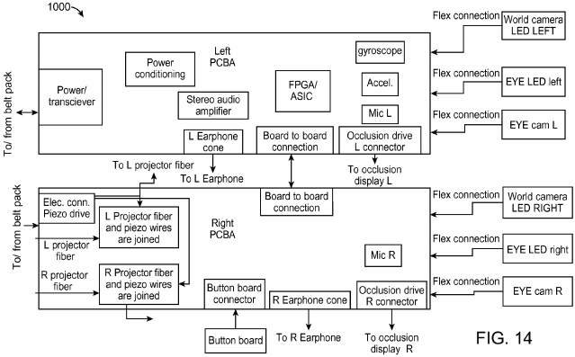
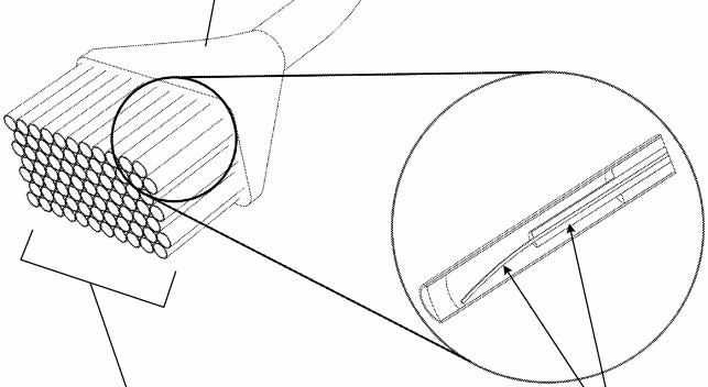
As we can see from the above diagram, we can expect two outward facing cameras, labeled as “world camara”. That said, the text of the patent implies there could be more than two, stating “one or more right outward facing or world view cameras [per side]”. At this point it is unknown how many cameras will be included on the system nor is it known how much Magic Leap is able to shrink these components. We do know they will be on the glasses and they are vital to SLAM processing.
The final use case for cameras can also be seen in the diagram above. At least two cameras will be pointed at your eyes. This is used to track your gaze and vergence such that the focal point and the direction of view can be obtained. It will also point an infrared LED at your eye to illuminate the eye for these cameras. This eye tracking will also be critical to the user interface. I imagine the question of “what are you looking at?” will be fundamental to how you interact with Magic Leap. It will potentially be the main interactive component similar to that of a mouse.
Clearly there is no way for me to verify this information at this time but it all adds up to sound like the product Magic Leap is trying to produce. Regardless if it turns out to be a consumer success or not, this is the first example of real innovation the tech industry has seen in some time. I am extremely excited to see what happens next for them and looking forward to the shake up this will put on the industry in general.
—
This post originally appeared on the Magic Leap-focused blog, GPU of the Brain by Jono MacDougall. It has been re-published here with permission from the author. Follow the blog on Twitter: @gpuofthebrain.